| Model | CV-5001 | ||
| Type | Controller | ||
| No. of pixels | • 512 (H) ? 480 (V), Approx 240,000 pixels • 640 (H) ? 480 (V), Approx 310,000 pixels | ||
| Camera input | Two colour/monochrome cameras (CV-035C/ S035C/H035C/035M/ S035M/H035M can be connected. Mixed connection is possible.) |
||
| Main processor for image processing | DSP | ||
| No. of registered settings | SD cards 1 and 2 can each hold 1000 programs (depending on the size of the SD card and the size of the programs), external switching possible |
||
| Number of screens that can be registered | Maximum 1000 screens for each program (depending on SD card size), Compressed saves possible |
||
| Internal memory capacity | SD card slot x2 (SDHC compatible) Compatible with OP-87133 (512 MB: standard in SD1 slot for CV-5501/5001), CA-SD1G (1GB: standard in SD1 slot for CV-5701), CA-SD4G (4GB: SDHC) |
||
| Window settings |
Measurement area | 128 locations per program | |
| Mask area | 4 locations per area | ||
| Colour extraction function (valid only when a colour camera is connected) | Colour binary, colour shade, Gray, RGB average gray (Colours can be specified numerically via HSV values) Compatible with 1:n copy |
||
| Measurement tool |
Area measurement | The shapes are rectangle, rotated rectangle, circle, oval, ring, arc or polygon (up to 12 sides), edge detection rectangle area or edge detection circular area |
|
| Position detection | Pattern search | • Multiple searches possible for both pattern area and search area. The shapes are rectangle, rotated rectangle, circle, oval, ring, arc, and polygon (up to 12 sides) • Pattern area can be masked (4 positions / area) |
|
| V-search | • Up to 256 patterns can be searched simultaneously for both pattern area and search area. The shapes are rectangle, rotated rectangle, circle, oval, ring, arc, and polygon (up to 12 sides) • Pattern area can be masked (4 positions / area) |
||
| ShapeTrax2 | • Multiple searches possible for both pattern area and search area. The shapes are rectangle, rotated rectangle, circle, oval, ring, arc, and polygon (up to 12 sides) • Pattern area can be masked (4 positions / area) |
||
| Edge position | • Angles can be measured. The shapes are rectangle, rotated rectangle, circle, oval, ring, arc or polygon (up to 12 sides), edge detection rectangle area or edge detection circular area |
||
| Trend edge position | • Circle or straight line can be measured from the detection results • Shapes are rectangle, rotated rectangle, ring and arc |
||
| Blob (Centre of gravity) | The shapes are rectangle, rotated rectangle, circle, oval, ring, arc or polygon (up to 12 sides), edge detection rectangle area or edge detection circular area |
||
| Inspection mode | Edge position | ||
| Edge pitch | |||
| Edge count | The shapes are rectangle, rotated rectangle, circle, oval, ring, arc, polygon (up to 12 sides), auto-adjusting rectangle or auto-adjusting circular area |
||
| Edge angle | Shape is rectangle. | ||
| Pair edge | The shapes are rectangle, rotated rectangle, circle, oval, ring, arc, polygon (up to 12 sides), auto-adjusting rectangle or auto-adjusting circular area |
||
| Trend edge width | Shapes are rectangle, rotated rectangle, ring and arc | ||
| Blob (characteristic quantities) | • Labels, center of gravity, main axis angle, area, feret diameter, perimeter, roundness • The shapes are rectangle, rotated rectangle, circle, oval, ring, arc or polygon (up to 12 sides), edge detection rectangle area or edge detection circular area |
||
| Stain detection | • Subtract stain detection by using subtract filter • Stain grouping function supports multiple stain detection and position measurement • The shapes are rectangle, rotated rectangle, circle, oval, ring, arc or polygon (up to 12 sides), edge detection rectangle area or edge detection circular area • Supports measurement of the colour image using fine colour |
||
| Trend edge flaw | • The shapes are rectangle, circle, oval, ring, arc, and polygon. • Supports flaw detection using straight lines, circles, ovals, and free-form straight lines as reference models. |
||
| Intensity inspection | The shapes are rectangle, rotated rectangle, circle, oval, ring, arc, polygon (up to 12 sides), auto-adjusting rectangle or auto-adjusting circular area |
||
| Colour (only when a Colour camera is connected) | • RGB and HSB measurement supported • The shapes are rectangle, rotated rectangle, circle, oval, ring, arc or polygon (up to 12 sides) |
||
| Geometry | • Calculation result can be reflected • Shapes are point, line, and circle |
||
| OCR | • Character recognition for max. 2 lines of 20 characters per line • Shape is rectangle • Built-in date/time encryption support function |
||
| Interface | Control input | External trigger input | 2 points EV compatible input rating: 26.4 V or less, 3 mA or more 2-camera simultaneous capture/individual capture can be selected. Individual trigger delay (0 to 999 ms) can be selected for each trigger input |
| Control input | 18 inputs Input rating 26.4 V or less, 2 mA or more |
||
| Control output | Universal output | 27 outputs NPN (including two FLASH outputs linked to external trigger.) | |
| Total comparator output | 1 output, NPN open collector, maximum 50 mA (30 V or less) Supports total status hold control and one shot output (1 to 9999 ms) |
||
| Monitor output | SVGA 800×600 (24-bit colour 60 Hz) | ||
| Run indicator | Power, Error LED display | ||
| RS-232C | Numerical value output, image data (compressible) and control input/output enabled. Can be used simultaneously with other communication ports. Maximum baud rate of 115200 bps is supported. Do not use to connect to PLC link, CC-Link, or EtherNet/IPTM |
||
| Ethernet | Numerical value output, image data (compressible) and control input/output enabled. Can be used simultaneously with other communication ports. 100BASE-TX/10BASE-T |
||
| USB | Numerical value output, image data (compressible) and control input/output enabled. Can be used simultaneously with other communication ports USB2.0 HI-SPEED compatible |
||
| PLC link | Numerical value output and control input/output using the RS-232C port or Ethernet port enabled. Following PLCs are supported via link unit*1: • KEYKENCE CORP.: KV-700 series, KV-1000 series, KV-3000 series, KV-5000 series, KV-5500 series • Mitsubishi Electric: A series (RS-232C only), Q series, L series • OMRON: SYSMAC C series (RS-232C only), CJ/CJ1 series • Yaskawa Electric: MP900 series (RS-232C only)/MP2000 series Do not use to connect to CC-Link, RS-232C, or EtherNet/IPTM |
||
| CC-Link | By connecting the optional CC-Link unit CA-NCL10E, numerical value input/ output and control input/output are enabled. • Supports remote device station, Ver. 2.00/1.10 • Do not use to connect to PLC link, RS-232C, or EtherNet/IPTM |
||
| EtherNet/IPTM | Numerical value input/output and control input/output enabled while using an Ethernet port • Supports periodic communication (Max. 1436 bytes), supports message communication • Up to 128 units can be connected • Compliant with compliance test Version.A5 • Do not use to connect to PLC link, RS-232C, or CC-Link |
||
| Illumination control | By connecting the optional illumination expansion unit, LED illumination (12 V, 24 V) and intensity control are enabled. • 2 channels per unit, connect up to 4 units • Supports multi-pattern illumination function |
||
| Continuous capture function | • 1 to 32-time multi-measurement (maximum, minimum and average values) • Error values can be excluded from the measurement result |
||
| Execution condition setting function | Can set whether to execute the results (OK/NG) for other measurement and calculation windows in each measurement window. |
||
| Image capturing setting function |
Processing area setting function | 240,000 pixels (512 (H) x 480 (V)) or 310,000 pixels (640 (H) x 480 (V)) of the 320,000 pixels are used for the process area. However, when CV-H035C/H035M is connected, support is only provided for 240,000 pixels of the 310,000 pixels used for the process area. |
|
| Scan mode (valid only when a monochrome camera is connected) |
Progressive/interlace selectable | ||
| Capturing start/end line setting function | Desired capture start/end line can be set within the image capture range. CV-H200C/H200M cannot capture fewer than 100 lines. |
||
| Correction functions |
Position adjustment | Batch, individual (maximum 128 settings), X, Y, ±180° rotation. | |
| Camera gain adjustment | Sensitivity adjustment, offset, and span adjustment (RGB batch/individual and span can be set for each of 16 brightness levels. RGB individual setting can be supported when colour camera is connected.) |
||
| White balance adjustment (valid only when a colour camera is connected) | Manual setting using white paper | ||
| Image inversion function | Can generate mirror images | ||
| Scaling function | X and Y calibration setting for each camera. Conversion from measurement values and calculation values is supported. |
||
| Filter function | Count | The same type of filter can be used up to 9 times. 13 steps. (For binarization and subtract only: 1 step/window) |
|
| Type | Expand, shrink, average, median, edge sharpening, edge extract X, edge extract Y, Sobel, Prewitt, Roberts, Laplacian, binary, subtract, illumination adjustment, contrast conversion, image extraction, image shade correction, blur |
||
| Display language | Japanese/English/German/Italian/French/Traditional Chinese/Simplified Chinese selectable |
||
| Calculation function |
Numerical operation |
No. of settings | 128 calculations/1 program |
| Arithmetic operation | +, -, x, ? | ||
| Arithmetic function | Square, exponential, counting fractions as one, round-off fractions, maximum, minimum, average, average within range, square root, absolute value, remainder, distance, angle, sin, cos, tan, asin, acos, atan, ? |
||
| Comparative operator | <, ==, Not | ||
| Geometric calculation | Distance between 2 points, angle of line segment, circle radius, circle center, average angle, straight line, cross point, distance between a point and a straight line, straight line angle, angle between the two crossed lines, perpendicular line between a point to a line, perpendicular bisector, midpoint |
||
| Coordinate conversion function. | Coordinate system conversion, rotating matrix | ||
| Type conversion function | Coordinate constant conversion, constant coordinate conversion, angle unit conversion |
||
| Logical operator | AND, OR, NOT, XOR | ||
| Sort function | Maximum value index output, minimum value index output | ||
| System function | Number of measurement times, measurement time, year, month, day, time, minute, second | ||
| Time axis operation function | Previous measurement result acquisition operator | ||
| Command memory | 1000 command memories that can be rewritten from external devices or the remote control console during operation are installed. |
||
| Support functions |
Statistics analysis | No. of data | Max. 20000 data (can be saved into an SD card in a batch) |
| Statistical items | Maximum, minimum, average value, deviation (3?), total status OK/NG times | ||
| Screen save (valid when monochrome and colour cameras are connected) |
The following number of screens can be saved in the system’s memory: • Maximum 511 images (monochrome camera) • Maximum 255 images (monochrome camera in 310,000 pixel mode) • Maximum 508 images (colour camera) • Maximum 253 images (colour camera in 310,000 pixel mode) (These are the maximum values with only one camera connected, and [Condition] set to [All Images].) |
||
| Programming aid functions |
Image Zoom | Between 4% and 1600% during setting or operation (6% and 2500% during full screen display) (Size can be set for each screen while displaying multiple screens.) |
|
| Edge derivative wave display | Edge waveform can be graphically displayed during setting or operation, and edge intensity and measurement values (some are not supported) can be displayed during setting. |
||
| Profile display | Trend edge position and gap can be graphically displayed during setting or operation. |
||
| Stability display | Stain detection (stain level) is displayed during setting or operation. | ||
| Cutout projection waveform display | OCR automatic cutout waveform graphics can be displayed during setting or operation |
||
| Shift all windows | Selected windows from an identical camera or an identical registered image can be shifted in the desired XY direction in a group. |
||
| Flaw level waveform | The flaw level waveform of the trend edge tool can be displayed as a graphic in Program or Run mode. |
||
| Display template setting function |
No. of display templates | 10 templates/1 program (within which 4 templates are specified values), externally selectable |
|
| No. of screens that can be displayed simultaneously | Max. 5 screens can be displayed at the same time (when 5 scr. (HORIZONTAL)/5 scr. (VERTICAL) is selected). |
||
| Hold image | Up to the past three images (NG images) can be displayed as hold images. Measurement results and measurement time can be viewed. (The number of displayable times varies between 0 and 3 depending on camera’s connection state |
||
| Screen customisation function |
No. of customised screens | 10 screens/1 program | |
| Custom item | Character string: Measurement value (decimal point can be specified), result, custom character, graphics, active text |
||
| Measurement result interlink | • Display colour can be changed according to the result for figures and custom characters. • Can set a message in the allocation table that relates to the measurement value (active text) |
||
| Operation rewrite function | • Upper/lower tolerance or command memory can be rewritten during operation. • Supports illumination adjustment during operation (when CA-DC21E is connected) |
||
| Emulation function | Built-in emulation function that can create new program data and save data on CV-5001SE in the FE format for the CV-3001 Series SE, SEII, and SEIII, and the CV-5001 Series. |
||
| Program file update function | The program data used on the CV-3001 Series or CV-5001FE can be converted into the program data format for the CV-5001 Series second edition. |
||
| Custom menu function | Shortcut menu to a desired program screen can be created (20 menus/program). | ||
| Memory card save function (SD2 slot only) | • Measurement value, judgment result, NG count, measurement image (compressible), stored image (compressible), captured image, statistics analysis data, RS-232C communication log, program data (only setting content can be saved to both SD1 slot and SD2 slot) • Can save data during test run (except for program data) |
||
| Others | Screen capture function, password function, re-test function, file management function, I/O monitoring, RS-232C monitoring (with log save function) |
||
| Rating | Power voltage | 24 VDC ±10 % | |
| Current consumption | 2.2 A (2 cameras at maximum load) | ||
| Environmental resistance | Ambient temperature | 0 to +50 °C | |
| Relative humidity | 35 to 85 % RH (No condensation) | ||
| Weight | Approx. 1,250 g | ||
| *1 Some models also are compatible with the RS-232C, Ethernet ports in the system. |

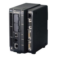
Датчик идентификации Keyence CV-5001
Digital Image Sensor/Controller
Описание
Получить КП
Для получения коммерческого предложения, пожалуйста, вышлите ваш запрос на электронную почту info@keyence-datchiki.ru с указанием требуемых позиций и реквизитами компании.
Похожие товары
Закрыть
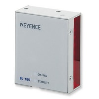
Датчик идентификации Keyence BL-180SO(7030)
Ultra Small CCD Barcode Reader, Front Type
Закрыть
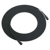
Датчик идентификации Keyence NX-C03R
Advanced RFID System Extension Cable 3 m
Закрыть
Датчик идентификации Keyence NX-C08R
Advanced RFID System Extension Cable 8 m
Закрыть
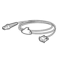
Датчик идентификации Keyence OP-77468
Replacement Cable for BL-N70R
Закрыть
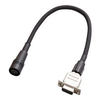
Датчик идентификации Keyence OP-80616
Round 12 pin connector - D-sub 9 pin Conversion connector (0.2 m)
Закрыть
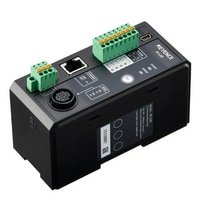
Датчик идентификации Keyence N-L20
Communication unit Ethernet connection type
Закрыть
Датчик идентификации Keyence OP-77466
Replacement Cable for BL-N70V
Закрыть
Датчик идентификации Keyence BL-1351HA
Ultra Small Digital Barcode Reader, High-resolution Type, Side Raster